CLMBR 02 Assembly GuideUpdated 5 months ago
| Applies to the Following SKUs: |
| CLCN22 |
| CLCN23 |
|
CLPR22 |
|
Tools Required | |
| Ratchet | 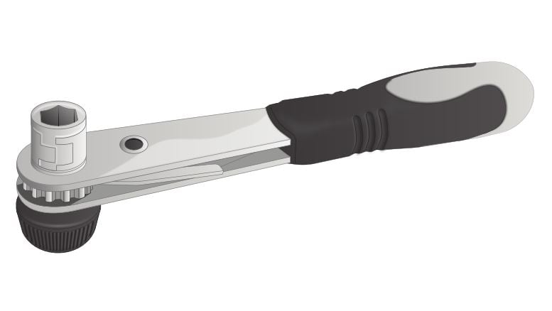 |
| 6mm Hex Key | 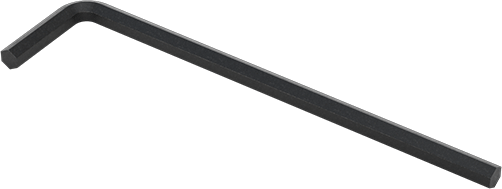 |
| 6mm Hex Bit | 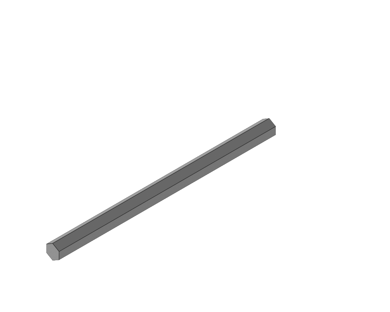 |
| Phillips Head Bit | 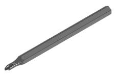 |
| Parts Required | |||||
| SKU # | ID | SKU Description | QTY | Reference Image | |
| CN02-FA-320 | A | PIN - QUICK RELEASE 6X25MM | 2 | 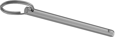 | |
| CN02-FA-410 | B | SCREW - M10X1.25X50 BHC | 2 | 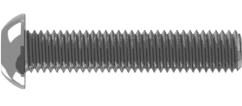 | |
| CN02-FA-409 | C | SCREW - M10X1.25X25 BHC | 8 | 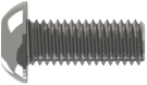 | |
| CN02-FA-408 | D | WASHER - FLAT M10 | 10 |  | |
| CN02-FA-369 | G | SCREW - M8X1.25X110 SHC | 4 | 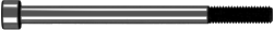 | |
| CN02-FA-430 | I | SCREW - M5X0.8X30 BHP | 2 | 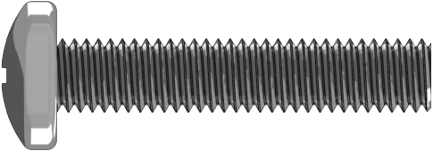 | |
| CN02-BA-007 | E | ASSEMBLY - LEVELING FOOT | 2 | 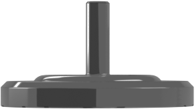 | |
| CN02-AC-311 | F | SADDLE - DIP BAR | 2 |  | |
| CN02-CC-009 | H | ASSEMBLY - KNOB | 1 |  | |
| CN02-AC-302 | J | HOLDER - WATER BOTTLE | 1 | 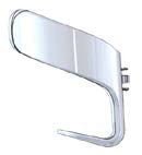 | |
Procedure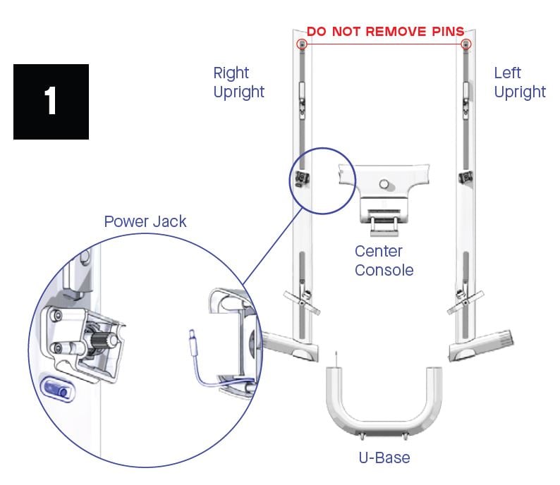
- Lay out all parts. Do not remove pins from upright upper pulleys until machine is fully assembled.
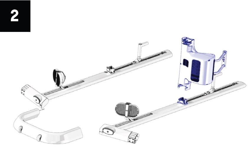
- Lower console onto left upright.
CLMBR Tech Pro Tip: With upright pins still installed, the pedal or handle can be moved up and down to help align couplers. Wiggle the pedal until the center console slides into place.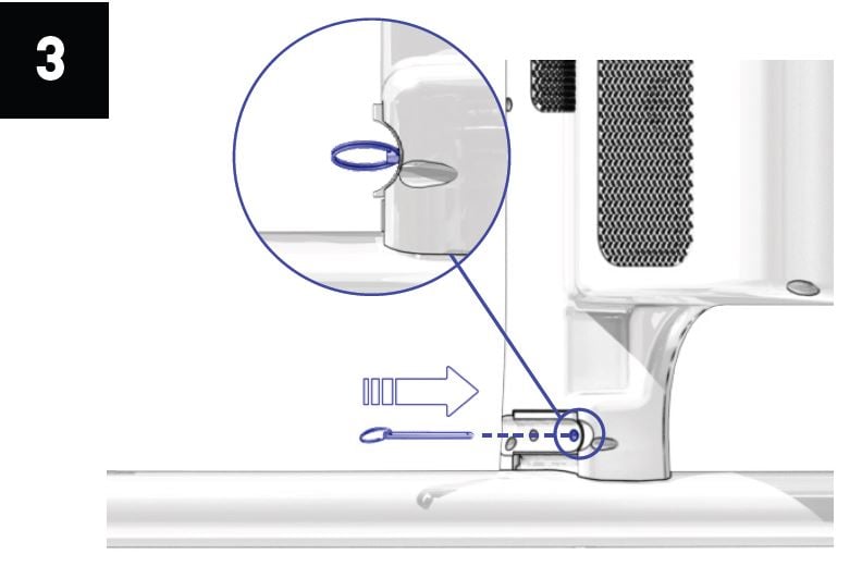
- Insert Console Pin (A) into upright coupler and console. Ensure the ring on the pin sits flush in the curved surface. Rock the console to help align the holes.
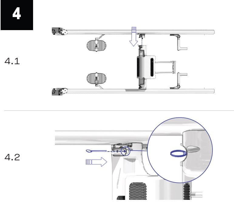
- Lower the right upright onto the console. (Fig. 4.1) Insert Console Pin (A) into upright coupler and console. (Fig. 4.2)
CLMBR Tech Pro Tip: With upright pins still installed, the pedal or handle can be moved up and down to help align couplers. Wiggle the pedal until the center console slides into place.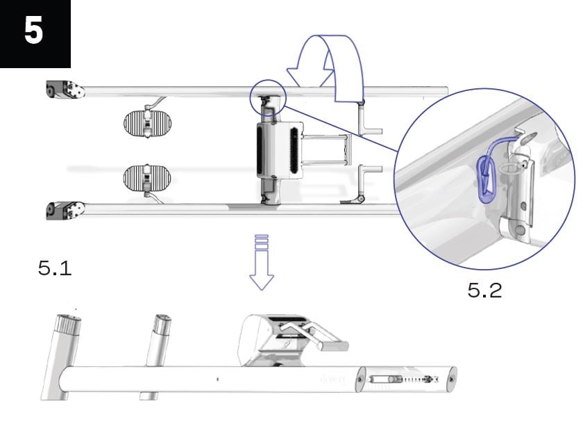
- Rotate the machine down to the floor. (Fig. 5.1) Plug the console power cord into the right upright jack. (Fig. 5.2)
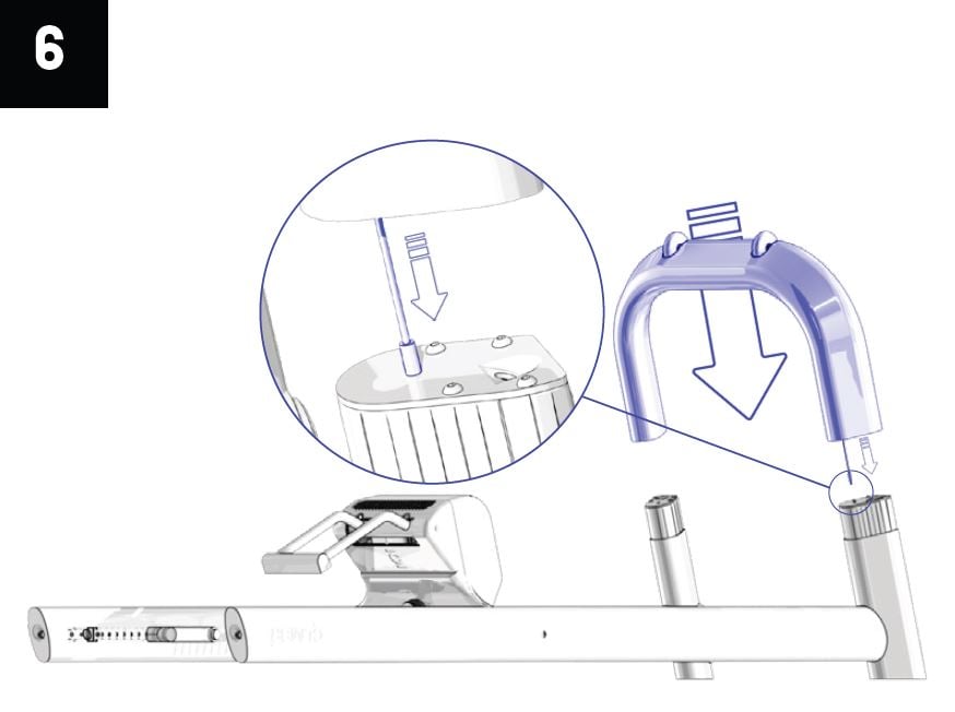
- Hold the U-Base above the ankles and plug the cable into the jack on the ankle face.
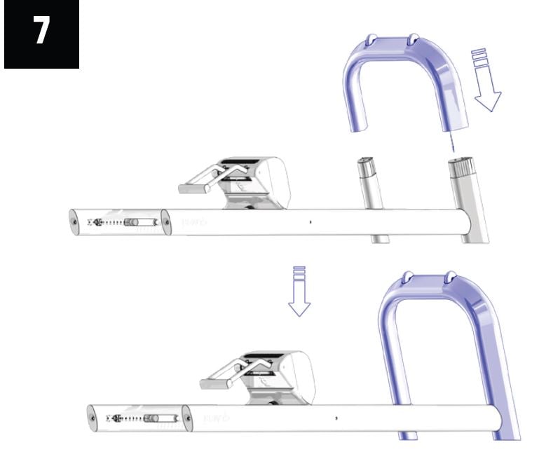
- Slide the U-Base onto the upright ankles. Ensure both sides slide on at the same rate and the cable does not get pinched.
CLMBR Tech Pro Tip: If the base doesn't install easily, ensure the uprights are relatively parallel and rock the base back and forth to slide it into position. If it is stuck on the last 0.5-1", use the long bolts (B) to pull the base into the ankles by tightening them first.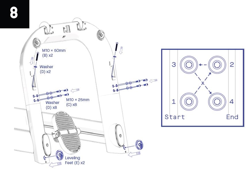
- Start threading 10 (B & C) bolts with washers (D) by hand in the u-base. Tighten both long bolts first. Then, tighten 4 short bolts on both sides in an “X” pattern. Thread Leveling Feet (E) into uprights.
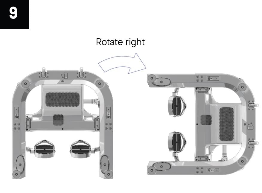
- Rotate the machine on its side.
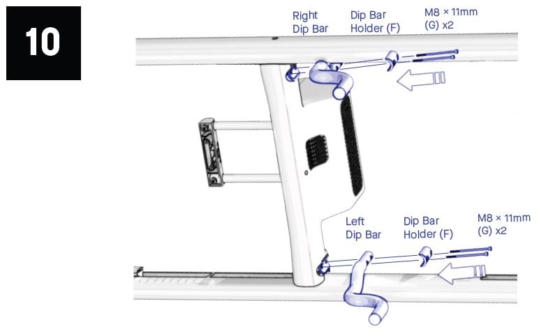
- Install 2 bolts (G) through one Dip Bar Holder (F) and dip bar into the coupler and console. Repeat for other dip bar. If bolts do not start threading, rock console to help align holes. Ensure dip bars curve down and out from under machine.

- Push the display tubes all the way forward. Rotate the machine on its back.
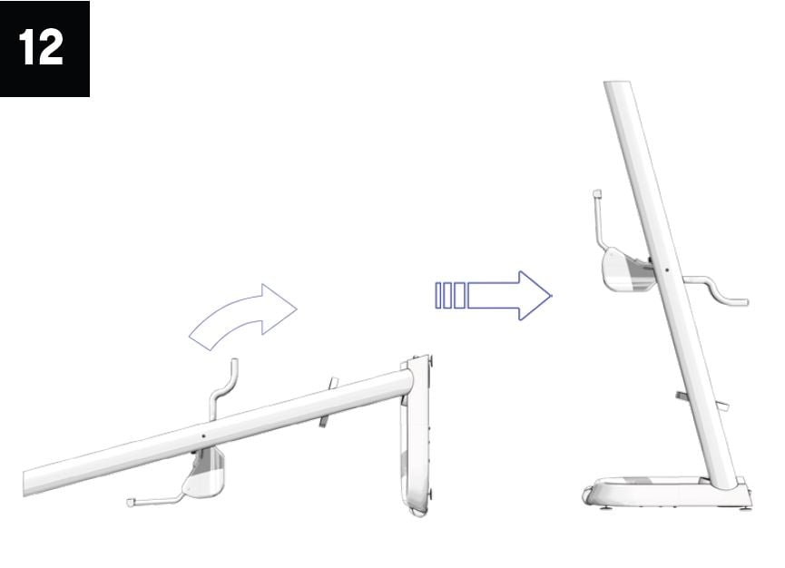
- Raise the machine to standing.
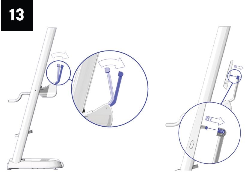
- Push the display tubes back and slide the display onto the mounting bracket.
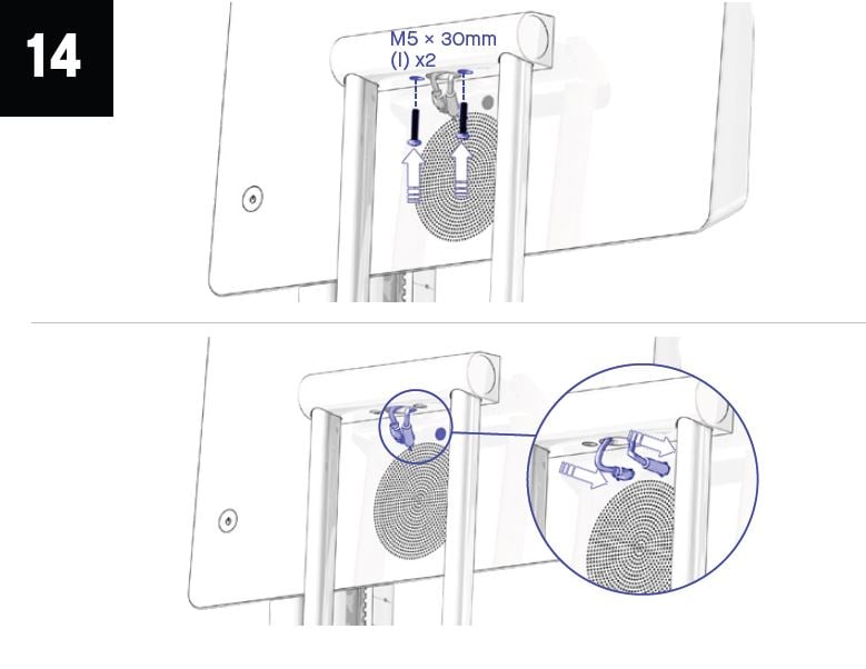
- Install 2 display mounting screws (I). Connect power and data cables on back of display.
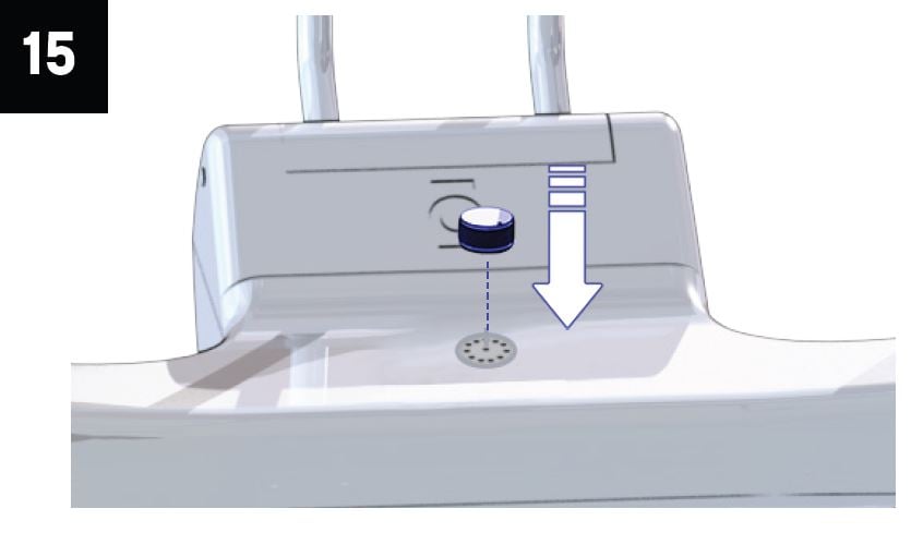
- Slide the Resistance Knob (H) onto the console housing shaft by aligning the D-profiles. Press down firmly to full seat the knob. Check that there is a clicking sound when the knob is turned.
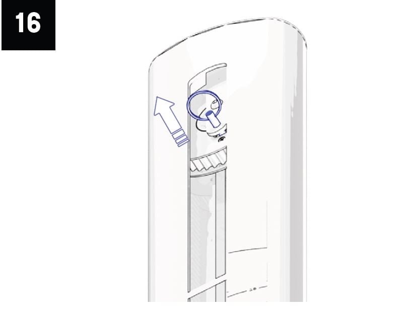
- Remove pin from the upper pulley on both uprights.
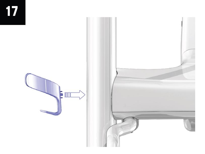
- Install Bottle Holder (J) on either upright.
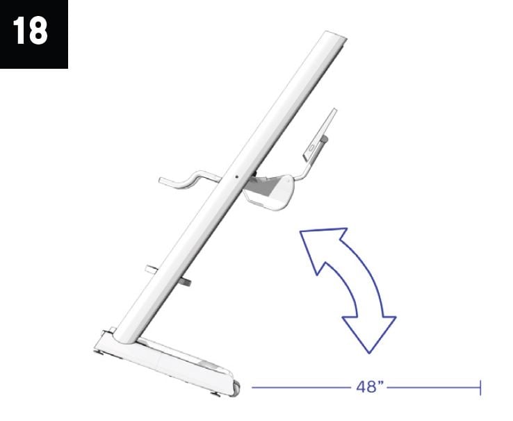
- Rock machine back on wheels and move to desired location.
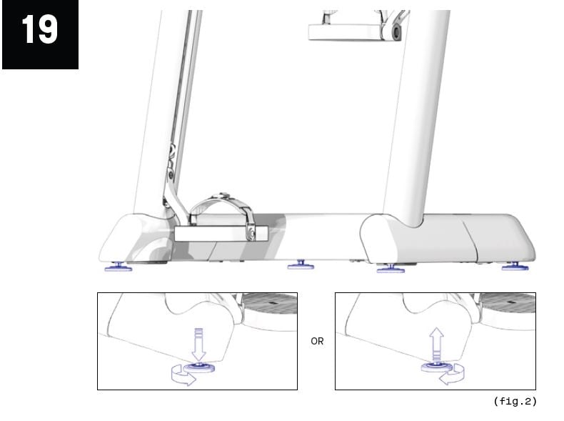
- Level machine by adjusting feet underneath the machine.
- Connect power supply to U-Base.
- Verify correct operations:
- Machine turns on
- Handles adjust smoothly
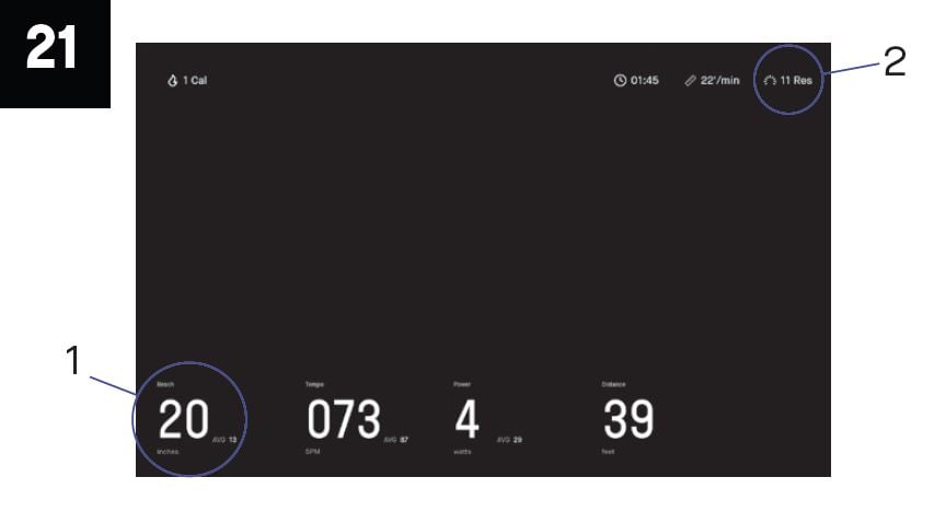
Start a workout and confirm:
- No abnormal sounds
- 1-11 resistance (1)
- 20 inch max reach (2)
Download a copy of the CLMBR 02 User Manual, or a printable version of this assembly guide below: